Power And Swr Meter Arduino : USB/Serial SWR Meter: i1wqrlinkradio.com / Jul 28, 2021 · adjust and test rf matching networks and rf amplifiers without applying power.
Power And Swr Meter Arduino : USB/Serial SWR Meter: i1wqrlinkradio.com / Jul 28, 2021 · adjust and test rf matching networks and rf amplifiers without applying power.. Jul 28, 2021 · adjust and test rf matching networks and rf amplifiers without applying power. Usually the swr meter does show some reflected power with this test. However this would result in approximately 500 µa of idle current constantly flowing through r4 into pin 7 while the system is turned. This posting is the c++ arduino uno processor code for an experimenter's variable voltage transformer. Read your directions for checking the swr.
This posting is the c++ arduino uno processor code for an experimenter's variable voltage transformer. Read your directions for checking the swr. A complete schematic package and a spreadsheet with parts info for all the components on the pcb logic controller for a deluxe high voltage power supply. james garland: In theory the arduino could directly drive the gate of the fet q1 without using q2 as a buffer; Usually the swr meter does show some reflected power with this test.
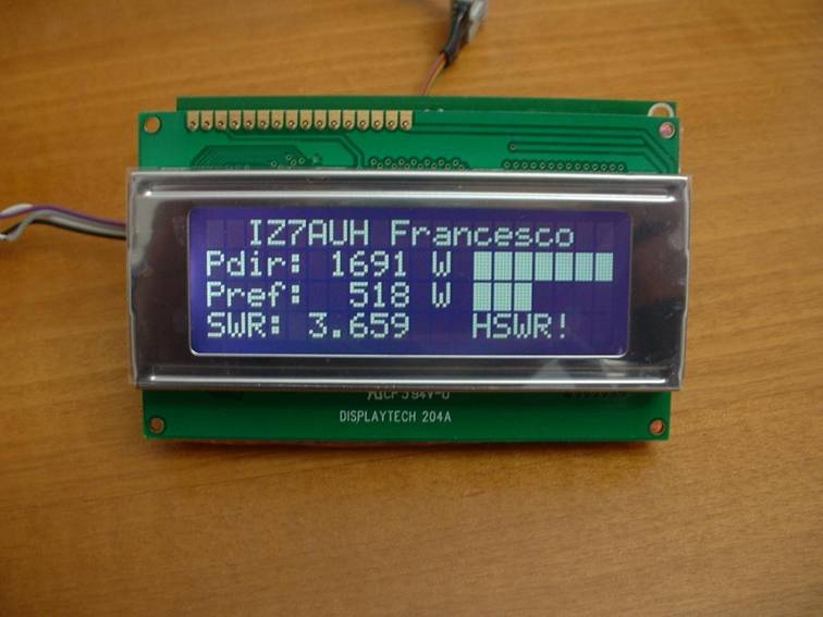
HF + 6m LCD RF Power and SWR meter 1500W from digilander.libero.it However this would result in approximately 500 µa of idle current constantly flowing through r4 into pin 7 while the system is turned. Mar 07, 2021 · the arduino can power down the system anytime by setting digital output pin 7 to low, thus switching off q2 and q1. Check your swr on channel 1 and 40. Alternately, a coupler with diode detectors can also be used. I just have to key the mike to see the swr. The swr meter should show a standing wave ratio of approximately 1:1.5 or lower. It should be around 1.5 across the band. Some meters you have to zero.
A complete schematic package and a spreadsheet with parts info for all the components on the pcb logic controller for a deluxe high voltage power supply. james garland:
Mar 24, 2018 · the same circuits can be used for the rf power coupler and the ad8307 as in the original power and swr meter project, however a few new builds are shown below. However this would result in approximately 500 µa of idle current constantly flowing through r4 into pin 7 while the system is turned. The swr should be ok with this if your solder joints are good. See appropriate #defines in the pswr_x.h file, included in the source code. The swr meter should show a standing wave ratio of approximately 1:1.5 or lower. Read your directions for checking the swr. I just have to key the mike to see the swr. Usually the swr meter does show some reflected power with this test. A complete schematic package and a spreadsheet with parts info for all the components on the pcb logic controller for a deluxe high voltage power supply. james garland: Alternately, a coupler with diode detectors can also be used. Mar 07, 2021 · the arduino can power down the system anytime by setting digital output pin 7 to low, thus switching off q2 and q1. Some meters you have to zero. In theory the arduino could directly drive the gate of the fet q1 without using q2 as a buffer;
Check your swr on channel 1 and 40. Usually the swr meter does show some reflected power with this test. It's also possible to test with a half wavelength of wire. I just have to key the mike to see the swr. Read your directions for checking the swr.
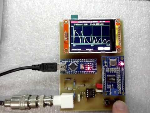
Arduino SWR Scanner by SP3NYR - YouTube from i.ytimg.com Some meters you have to zero. Mine is automatic when it is in the swr mode on the radio. See appropriate #defines in the pswr_x.h file, included in the source code. The swr meter should show a standing wave ratio of approximately 1:1.5 or lower. Jul 28, 2021 · adjust and test rf matching networks and rf amplifiers without applying power. The swr should be ok with this if your solder joints are good. It should be around 1.5 across the band. Mar 24, 2018 · the same circuits can be used for the rf power coupler and the ad8307 as in the original power and swr meter project, however a few new builds are shown below.
Mar 24, 2018 · the same circuits can be used for the rf power coupler and the ad8307 as in the original power and swr meter project, however a few new builds are shown below.
A complete schematic package and a spreadsheet with parts info for all the components on the pcb logic controller for a deluxe high voltage power supply. james garland: See appropriate #defines in the pswr_x.h file, included in the source code. Mar 24, 2018 · the same circuits can be used for the rf power coupler and the ad8307 as in the original power and swr meter project, however a few new builds are shown below. It should be around 1.5 across the band. Mar 07, 2021 · the arduino can power down the system anytime by setting digital output pin 7 to low, thus switching off q2 and q1. Usually the swr meter does show some reflected power with this test. Jul 28, 2021 · adjust and test rf matching networks and rf amplifiers without applying power. Mine is automatic when it is in the swr mode on the radio. Alternately, a coupler with diode detectors can also be used. In theory the arduino could directly drive the gate of the fet q1 without using q2 as a buffer; The swr meter should show a standing wave ratio of approximately 1:1.5 or lower. It's also possible to test with a half wavelength of wire. Some meters you have to zero.
Check your swr on channel 1 and 40. However this would result in approximately 500 µa of idle current constantly flowing through r4 into pin 7 while the system is turned. The swr meter should show a standing wave ratio of approximately 1:1.5 or lower. Read your directions for checking the swr. I just have to key the mike to see the swr.
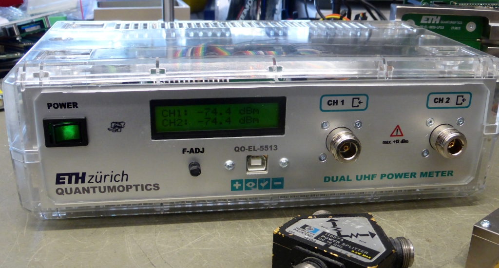
Arduino Shield ''NRVD'' from www.changpuak.ch Some meters you have to zero. Mar 07, 2021 · the arduino can power down the system anytime by setting digital output pin 7 to low, thus switching off q2 and q1. Mine is automatic when it is in the swr mode on the radio. Read your directions for checking the swr. This posting is the c++ arduino uno processor code for an experimenter's variable voltage transformer. It should be around 1.5 across the band. See appropriate #defines in the pswr_x.h file, included in the source code. However this would result in approximately 500 µa of idle current constantly flowing through r4 into pin 7 while the system is turned.
Read your directions for checking the swr.
Mar 24, 2018 · the same circuits can be used for the rf power coupler and the ad8307 as in the original power and swr meter project, however a few new builds are shown below. Mine is automatic when it is in the swr mode on the radio. The swr should be ok with this if your solder joints are good. Check your swr on channel 1 and 40. I just have to key the mike to see the swr. See appropriate #defines in the pswr_x.h file, included in the source code. Usually the swr meter does show some reflected power with this test. The swr meter should show a standing wave ratio of approximately 1:1.5 or lower. Some meters you have to zero. Mar 07, 2021 · the arduino can power down the system anytime by setting digital output pin 7 to low, thus switching off q2 and q1. It's also possible to test with a half wavelength of wire. However this would result in approximately 500 µa of idle current constantly flowing through r4 into pin 7 while the system is turned. It should be around 1.5 across the band.


0 Komentar